EOL resistor and Line monitoring using EOLR ? (end of line resistors).what are these terms?
EOLR Or End of line resistors .What are they? A specially made resistor???
They are ordinary resistors .As the name implies, they are connected at the end of the line…..!!!!
End of line resistors are resistors connected at the end of a signal loop . In Control systems and signal circuit,supervision of a loop can be done by the proper connection of resistors at the device end .By supervision of the loop means whether the loop is faulty or not . which means any wire break or short circuit ,ground fault etc in the loop. They make false alarms or false status .In control systems like security systems and fire alarm systems a false alarm is critical and may cause huge loss.So detecting the line fault in addition to the conventional device status is required .In simple terms we call this technique as Line Monitoring .The design of such systems should be done properly .
While establishing the wiring and circuit of such systems EOLR ( End of line resistors) plays as a important component of each signal loop .Or each zone etc .Let us examine how the circuit works .
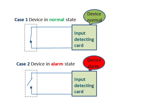
Ordinary signal loop -(No EOLR )
Let us take an example of an ordinary signal loop . A device which gives a discrete status is connected to a control room panel . No EOLR employed in this loop .The device is meant to give normal and activated or alarm status .(A pressure switch,a smoke detector, fire detector , level switch etc .) A close condition will regarded as normal state and open contact as alarm state .see below figure .
Device contact Close( max current) ——– normal
Device contact open (min /no current)——- Alarm
So That is the case .A receiving or detecting circuit checks the loop continuously .They receives either a maximum current or no current And they reports it as normal or alarm condition respectively .
What is the problem in this type of detection????
In the above case we can only gets two status of the field device.Device in normal condition or in alarm condition .What if the loop wire got shorted or got open?
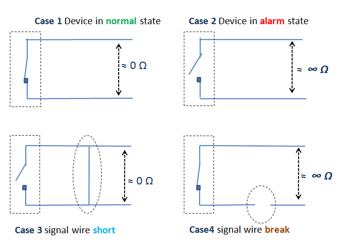
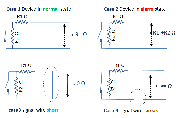
See the diagram .
In the above image ,see case3&4 .So in addition to the normal and alarm condition( case 1&2) ,there are two faulty status of the signal loop . For wire break and wire short.
So the four conditions of the loop are
Normal
Alarm
Loop short
Loop open.
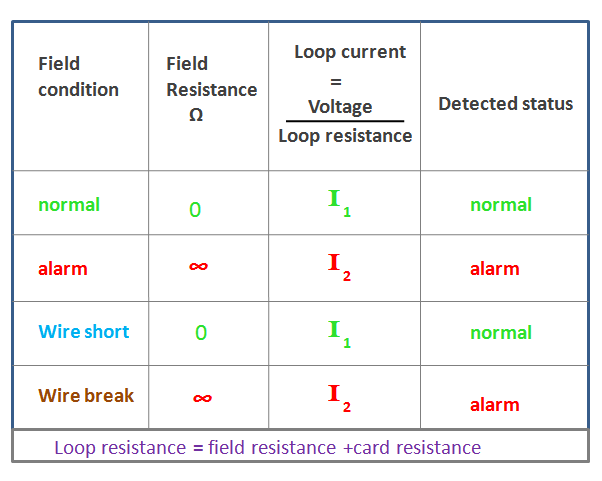
How an ordinary monitoring system respond to the above four cases .By ordinary it means the input card or monitoring devices is not designed to report line faults .You can see the system see similar status in wire break and wire short conditions .
Means it detects same loop current , when,
1 .Device in normal status and
2 .wire short .
And it detects same loop current when
1.Device in alarm status
and
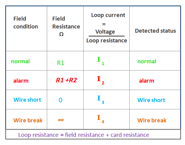
2.wire break see below table
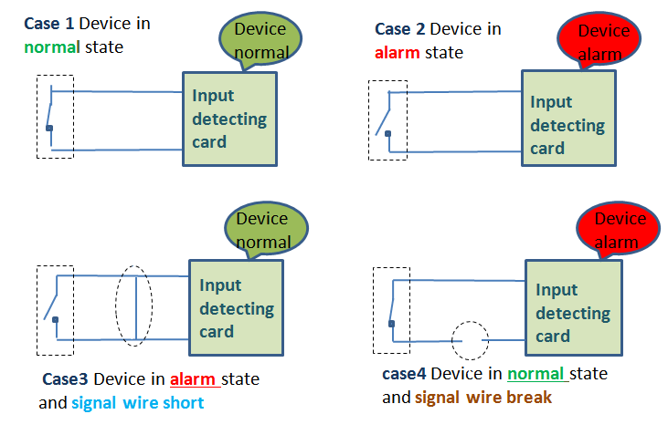
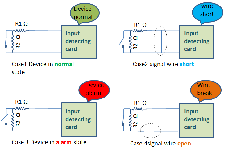
The loop current values (or loop resistance) are same in normal and wire short conditions .Also it is same in alarm and wire break conditions .So the system detects same current levels in different field conditions .Means the whole system doesn’t distinguish these different conditions .A monitoring card or control room input device reports same statuses at different conditions .see below diagram .The system only reports normal and alarm status .The loop or line is not monitored in this type of design
.see case 3 & 4
The input detecting card reports the status as normal in wire short conditions !!!!!!!
Also it reports alarm in wire break conditions?!!
why ordinary monitoring systems reports false status?
What we learned From the above examples ???
Why detecting circuit or input channel failed to detects these line faults (case 3&4)
We already learned
Two reasons
1. The monitoring device is designed or programmed to report these two conditions only .normal and alarm.(contact close or open)
2 .Another reason is similar current or field resistance values are fed to the detecting circuit in different field conditions .
The similar conditions are
1.Close contact and wires short
This conditions gives maximum current in the loop .Means a contact short results maximum current in the loop .Also loop wires short gives the same result .So these close contact and shorted loop are not distinguishable in such circuits .
2 .An open contact and wire break
This causes no current in the loop .And these open contact and wire break are not distinguishable in such circuits .
How to detect line faults?
So how to detect line faults in addition to ordinary normal and alarm status of the device.
1.Design and program a detecting circuit which detects these field status.
Normal
Alarm
Loop short
Wire break
So detecting circuit should be designed and programmed accordingly .It should detect the above four conditions .Means it should programmed or configured to detect these four conditions .
2.Arrange field circuit to give these four current levels .Means input card should receive different current values at different conditions .So it could easily distinguish these conditions.
But how?
Here it is …..use EOLR
End of line resistors.
Line monitoring using EOLR
A properly arranged resistors at the device end and a properly programmed i/o input card or module or detecting circuit will eliminate false alarms .And monitoring of the line can be done effectively .The value of resistors may depends upon the input channel current range limits .
See the above diagram .A field device is fitted with end of line resistors .One is in series and one in parallel with the loop .Both are connected at the end of the signal loop hence the name end of line resistors .Supervision of the loop can be done effectively with this arrangement .
See the four cases below . The four conditions are shown .And in four conditions we get the different field resistances . Accordingly we will get the four distinguishable levels of loop current .So these four current levels can be programmed as four status .See the below figure .End of line resistors are connected at the field end of the loop .Four conditions are shown . Field resistance values seen from the monitoring card or device is shown .
Let’s see the circuit conditions in these four cases. Means what are the values of loop current and field resistances .See figure below .You can see the system receives different loop current corresponding to the four field conditions.This is because of the arrangement of resistors at the device end .
See below table .
Line monitoring using EOLR
So the system detects different current levels in different field conditions .Means it has capability to distinguish these different conditions .It reports the line faults in addition to the conventional normal and alarm status . .Means the loop or line is monitored .See figure below.
..
See figure above .The four field conditions are fed to the input card by four different current levels .And the input card distinguishes these conditions
Note: This article only describes simple line monitoring methods and it’s basic concepts . More complex and advanced line monitoring systems and design are available and we will describe it in another article .