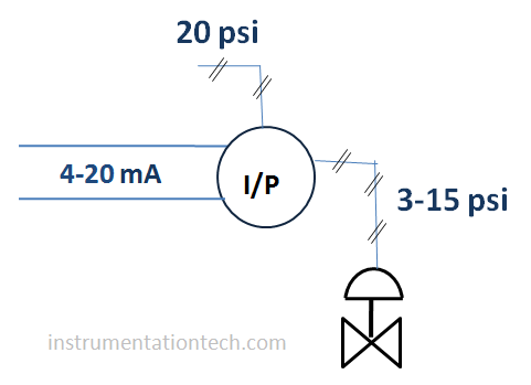
I/P converter or current to pressure converter is a commonly used device in instrumentation field . The device used to convert the electrical signal in to air pressure . It is mainly used for the operation of Pneumatically operated control valves .Pneumatically operated control valves need air pressure for their actuation .Means it is operated by a pneumatic output given to its diaphragm chamber .But in most cases our control signals are in electric form ( like 4-20 mA) .In such situation it is essential to convert the signal in electrical form to corresponding pneumatic signal. This is established through the device called l/P transducer .
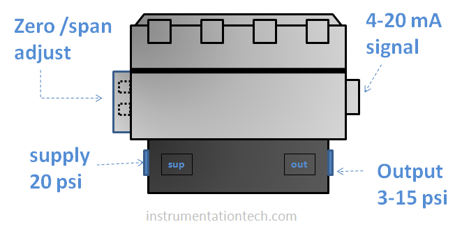
Usually the electrical signal is in milliamperes (4-20mA) and pneumatic output is ( 3-15psi) .Air pressure of 20 psi needed as a working supply pressure for the I/P .
Conversion to air pressure is done by regulating a air pressure in accordance with the incoming electrical signal through flapper nozzle arrangement.Air pressure of 20 psi is given to the I/P as supply pressure .
.Flapper nozzle type of design is greatly employed in pneumatic device s like I/P transducers, pneumatic transmitters etc.
I/P transducer working -Flapper nozzle arrangement
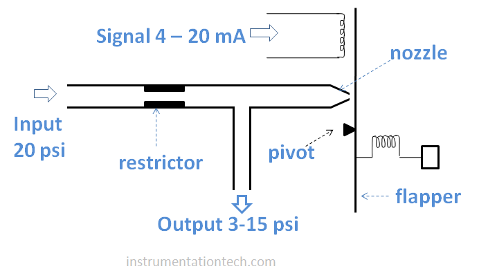
Flapper nozzle mechanism is a common arrangement used in pneumatic instruments and transducers.It creates a pneumatic output in accordance with a mechanical movement.The arrangement mainly consists of a thin flat plate called flapper and a nozzle through which supply air is fed.output line is also taken from the nozzle stream.see figure.The position of the flapper determines how much air to escape and how much the output pressure is .The more the flapper is close to the nozzle,the more the output is and vice versa .
I/p transducer working
The supply air is fed in to nozzle assembly through a small hole . Nozzle opening is restricted by small thin flat metal part known as flapper whose movement can be controlled by the input current signal 4-20mA..Air output is taken from the nozzle assembly .See figure . The flapper position determines the air output. The more flapper is near to nozzle the more will be the output and vice versa .
The current signal is fed in to a coil which causes it to magnetise and these magnetism cause the flapper to move. Varying the electrical signal cause the strength of the magnetic force to vary and also it affects flapper movement . And the variations of the flapper causes the output to increase or decrease as it restricts the nozzle .
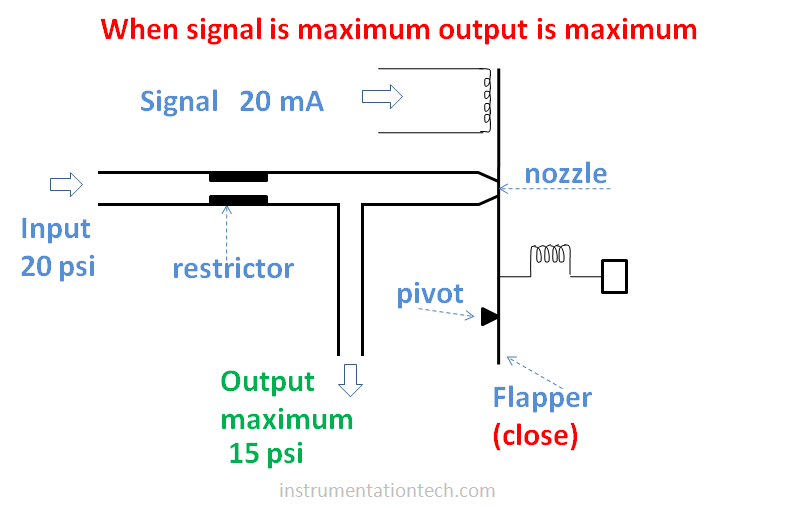
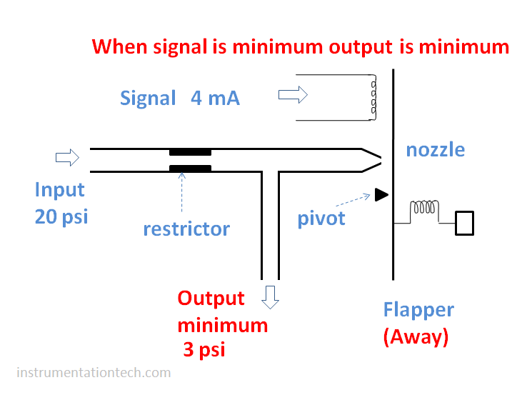
when the flapper close to the nozzle,the amount of escaping air is minimum and the output is maxiumum .see figure
.And if the flapper is away from the nozzle ,greater amount of air will escape through the nozzle and output will be minimum.
This way the input current is converted in to air pressure . Only a small part of air is fed in to the flapper nozzle assembly and pneumatic relay is used for the amplification . These booster relay and components for zero span adjustment to calibrate the devices,etc gives completion of the properly designed I/P transducer.