To bring the process in a required way is the ultimate aim in any industrial environment . process variables need to be monitored and controlled in a required fashion . parameters will affect the process . And it is desired to maintain these parameters within the specific values.This is for the correct outcome of the process .And this has to be employed through proper control methods . Various types of control modes and functions are executed in industries. This is for bring the process with the desired values of process variables .PID control ,a popular control mode implemented in many industrial applications.
Suppose we have a tank filled with a liquid and we want to control the level of the tank.one method to control the level is the gap control.That is maintain the level between two limits.we can establish this by using two level switches and proper control circuit like relay logic circuit or by using PLC I/o’s and program to do this.But if the process want the level to be continuously monitored and controlled for a specific setpoint.That is we need to keep level at a setpoint ,what will we do???The answer leads to the most effective form of continuous control employed in most of the industrial applications .PID control , Proportional Integral, Derivative, Control .
PID Control and PID Controller
PID control.
A control scheme used in continuous closed loop control .A target setpoint of a process variable is achieved and maintained by manipulating the controlled variable .
PID controller is a device which continuously receives a process variable signal as input and ,matches it with a desired value(setpoint) and make corrective actions through its output on the basis of control parameters like P,I,D values. They continuously try to bring the process variable to a setpoint .It is a most popular and effective form of closed loop continuous control employed in most of the industrial applications .
See figure below. A tank filled with a liquid needs it level to be maintained at some setpoint .A man continuously watches the level in the tank .He regulates the inlet flow to the tank by continuously adjusting the opening of the valve .He is doing this by watching the locally provided level indicator . He knows how fast the level is rising or falling and what amount of level needs to increase or decrease to reach setpoint etc.Based on this he make corrections by adjusting the valve continuously . He fine controls the valve when the level approaches setpoint by decreasing the opening rate and amount of opening of the valve .
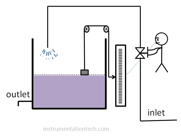
In this way he succeed to bring the level at setpoint and he continues to make corrections inorder to stay the variable at setpoint.
PID Controller
What if we replace the man in the above example with a device which will do the same job .The device is none other than PID controller. The below figure shows a PID loop.A level transmiter senses the level in the tank and transmits a proportional current signal ( like 4-20 mA) to the PID controller .The output of PID is a control signal to control a valve in the inlet .The setpoint is entered to the PID .
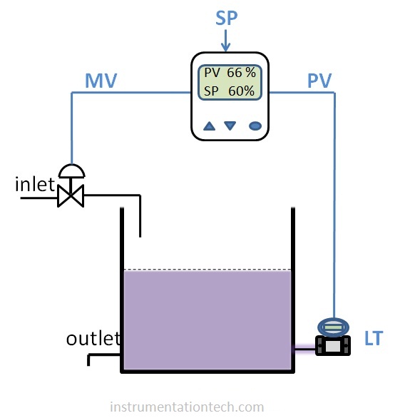
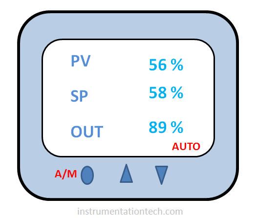
The controller continuously matches the setpoint and the process variable and calculates error .Here error means the difference in values between process variable and setpoint.And send an output to the control valve based on these error values and the P,I,D values . Suppose the level in the tank is 66% at an instant and setpoint is 60%. So inorder to bring the level to 60% the PID will send a signal to decrease the opening of control valve .This causes the level to decrease and it approaches to the setpoint . And PID controller continues its error calculations,and manipulating the output to maintain the PV at setpoint .This is how a PID controller works .Let’s learn some of the terms related to PID control .
PV -process variable
Process variable is the physical property that we need to measure and control.(ex.pressure, level,flow etc.). And in PID, the the present value of this parameter is termed as PV . In above example it is the level to be monitored and controlled in our process,and it’s value is the PV.
Set point
The desired value of process value.In PID controller or in PID interface in SCADA,or DCS,orPLC etc,this value need to be entered by the operator .Also in some cases PID control is provided with remote setpoint .
Error
The Difference in value between PV and setpoint is the error.PID controller continuously calculates error and changes output as based on this error and PID values.
Error = PV – Setpoint
Manipulated variable
The variable which need to be adjusted inorder to get the process variable to reach setpoint is called manipulated variable .In the example previously discussed it is the flow to the tank inlet that has to be controlled for the level control .
Output
It is the signal given by the PID controller to varry manipulated variable there by control the process variable or process value.In the previous example 4-20mA given to the I/P of control valve is the output of the PID controller .
P,I,D Values
In the above examples we have seen how PID controller works .It continuously compare the process variables to setpoint ,calculates error and provides output to bring the PV to setpoint
But how it manipulates it’s output??
This error and manipulated output indeed have certain relationship. And these output manipulation is based on certain parameters .
There are three basic parameters which determines the output manipulation .They tells controller how to changes its output according to error .They determines the amount,speed, duration and rate of output signal changes in accordance with the error .( Error means PV -SP) .These three parameters known as P,ID, terms means proportional ,integral, derivative terms .In simple words the functions of these parameters can be described as ,
Proportional Action tells How much correction should be applied.
Integral Action tells how long should the correction need to be applied
Derivative action tells how fast should the correction be applied .
PID control modes .
PID control
All the control actions can be used effectively by proper tuning of P,I,D parameters .The different possible modes a PID controller can establish are the following
P Proportional only
PI Proportional + Integral
PD Proportional + Derivative
PID Proportional + Integral + Derivative
It should be note that proportional mode is common.We can enable or disable the integral and derivative action but it is not possible to establish a control mode in PID Controller without proportional term and is meaningless . This is because the proportional function is the primary output generator . It generates output which is proportional to the error .In simple words Integral and derivative terms are for corrections and for elimination of the offset . PI and PID modes are the most used and most effective mode of control.Even PI control is enough for most of the closed loops if it is properly tuned .
Proportional action and proportional only control
The proportional output is a term which contributes to the control output so that it is proportional to the error
Proportional output =Kp×e
Where Kp is called proportional gain which determines how many times error has to be multiplied . It amplifies the error and provides the output .So the factor Kp is termed as proportional gain.
For example a 10% error with a proportional gain of 1 will produce a 10% proportional output
And if the gain is 2 the output will be 20 %
If the gain is 0.5 output is 5% and so on
Proportional Band
The gain can be also expressed as band.
Proportional band =100 % /Gain
gain = 0.5 Means Proportional band = 200%
gain = 1 means Proportional band = 100%
gain = 2 means Proportional band = 50%
The proportional band and gain represents the same.
Larger value of Kp makes large output change in response to the error . Making proportional gain high may give a faster response .Means target setpoint will be achieved in a short time .But this may result in oscillation in the process value about the setpoint . This is called overshooting .
Also smaller proportional gain gives stability .But response is slower .It may take more time to achieve a setpoint .
Proportional only control
In this mode only the proportional action alone is used.The main disadvantages of this control is it doesn’t eliminate the permanent offset caused due to the load changes .
proportional output can be expressed in this mode as
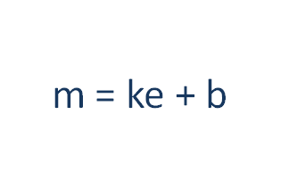
Where k s the proportional gain
e is the error
b is the bias.It is the output when there is no error
Proportional action only will not be sufficient for the accurate control of PV.Although Proportional term reduces error it has no capability to eliminate the error .proportional mode only make the output to change in proportional to the error .One of the main disadvantage of Proportional only mode is it results a ‘ offset ‘ a permanent error between PV and SP.
How offset happens
Why this happens ? Because proportional mode only responds to the change in error . Let us examine how offset happens with an example. consider the case we previously discussed .The PID controller is used in proportional only mode to control the level in the tank .PID is giving output proportional to error.As the Controller manipulating the output cause further decrease in error .And this error change cause controller to update the output . Controller do this job at every instant . Suppose a condition occurred .The inlet flow and outlet flow equals at some point.At this instant there is no further increase or decrease of level as the inlet and outlet flow are equal .And we know the control valve position is proportional to the present error And that error is not changing .So error continuous to exist .The result is a permanent offset or permanent error . As there is no change in error ,there is no change in proportional output .It stays at the previous value.This is one of the way the offset happens and proportional only Controller fails to eliminate that offset .
Integral action
The integral action is introduced to eliminate the steady state errors which is common in proportional only mode. How integral action works .Integration means summing .In PID Controller the errors are summed up over time and added to the proportional output.This process happens at every instant and as long as the error exists .When the error term goes zero this term vanishes Thus the integral control always try to pull the PV to setpoint . .Even a small error over a long time will make the integral term to grow and force the output to reach the extream thus providing maximum possible conditions for the PV to reach setpoint . In this way integral action helps to reset the error to zero . So it is also called reset action.
Integral time
It is the constant used to increase or decrease integral response .Its unit is Minutes per repeat or Repeats per minute .
Proportional+integral control
Integral action doesn’t works independently.It works along with proportional mode.The output of a PI controller can be written as
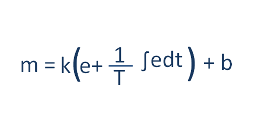
m is the controller output in PI mode .
Where k s the proportional gain
e is the error
T is the integral time .
b is the bias.It is the output when there is no error
Derivative action
In mathematics derivative actually means the rate or slope of a variation.In PID control the derivative term contributes to the rate of error change.Derivative control predicts the future of a variable change and provides output which is proportional to the derivative of the error .
Proportional+Derivative control
Derivative control works with proportional output and is called proportional+derivative control or PD control.The output of PD control can be expressed as
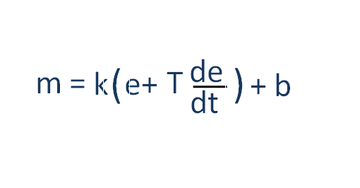
m is the controller output in PI mode .
Where k s the proportional gain
e is the error
T is derivative time.
b is the bias.It is the output when there is no error
Proportional+integral+Derivative control
PID control
All the control actions can be used effectively by proper tuning of P,I,D parameters .The main control schemes are,
It should be note that proportional mode is common.We can enable or disable the integral and derivative action but it is not possible to establish a control mode in PID Controller without proportional term and is meaningless . PI and PID modes are the most used and most effective mode of control.Even PI control is enough for most of the closed loops if it is properly tuned.
PID controller is a device which continuously receives a process variable signal as input and ,matches it with a desired value(setpoint) and make corrective actions through its output on the basisis of control parameters like P,I,D values. They continuously try to bring the process variable to a setpoint .It is a most popular and effective form of closed loop continuous control employed in most of the industrial applications .
Control action
Control action specifies the direction of the PID output change in response to the process variable change with respect to the setpoint . Proper direction must be employed otherwise PID control will never work .
Direct action.
Output change and process variable change keeps same direction.see below level control loop.A control valve is employed in the outlet .The valve is normally close .(Means 4 mA output signal in fully close position).So Inorder keep he level at set point what action should we chose? Suppose setpoint is 50% .And level also at setpoint .Suppose level increases to 60% .Then PID should increase the valve opening to reduce the level .Also if the level decreases say to 40% ,then PID should decrease the valve opening .So pV change and output change should keeps same direction .So a Direct action is needed here .
Reverse action .
Suppose in the above example ,if the control valve is normally open ,what should be the control action .We can easily say .We need reverse action in this case . Because output change and pv change should be in opposite directions so as to work the PID control .
Determining Control action
Direct action and reverse action should be determined by evaluating the process condition and normal condition of the final control element .In the above example , control valve in the PID loop is functioning at the outlet.If it was in the outlet,then the control action should change .So we have to consider all these factors . And identify what should be done at output to work the PID control .
Let us analyse a situation .A tank containing a liquor.The liquor temperature has to be maintained at a desired temperature .It is established by passing steam through the steam coils inside the tank .A normally open control valve is used to control the steam flow.What should be the PID action? Direct or reverse?
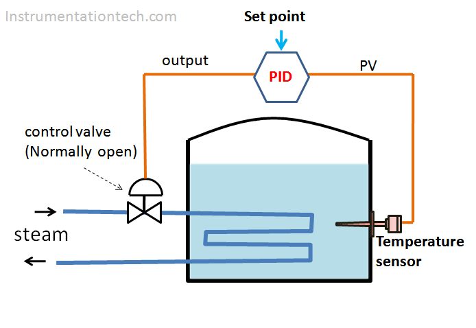
Assume temperature is above or below setpoint .
Let’s select it is below setpoint .Then valve should increase its opening. As it is a normally open valve,for full opening output should go to 4- mA .means control output should decrease. So as the pv goes decreasing output should decrease to bring the pv back to setpoint .Here PV change and output change should be in a same direction for the working of PID control.So PID action should be Direct .
PID basic connections

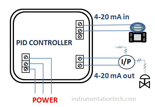
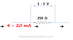
PID control loop connections
Above figure is a simple representation of a PID controller with its connected input and output .The input is a 2 wire transmitter with a 4-20mA as input .These 4-20 mA signal corresponds to PV .The setpoint should be entered in the controller .The output 4-20mA is sent to the control valve .
PID control in Control systems (DCS,PLC, SCADA etc .)
How PID control implemented in modern control systems like PLC,DCS or SCADA. In electronic type control systems,they use dedicated electronic devices for PID controlling .Known as PID controller .But modern control systems are so advanced today . They implement PID control with software integration . we only need to configure the PID block in these contol systems and link it in to the corresponding analogue input and output .
Tuning of a PID controller
The ultimate aim of a PID controller is to bring the process variable to setpoint . Process disturbances, process load variations ,etc cause error (Deviation from setpoint ) and PID will act accordingly . Oscillation of the process variable about a setpoint is common after a large disturbance . PV oscillate about the setpoint and finally it settles at setpoint in response to the action of the PID controller .Correct balanced values of P,I,D parameters are needed for the smooth PID response.And proper PID response for a specific process is achieved by tuning these parameters . An improper tuning may results large and many oscillations,slow response etc .