This article describes the design and working of a simple hardwired alarm annunciator circuit .
What is alarm annunciator
Alarm annunciator is a warning and indicating system of process conditions which generates audible and visual alarms during a fault or alarm conditions .
Why we need alarm annunciation???
In a process plant or industrial environment the operations or events are depend on many factors ,logic , parameters etc with proper control and automation systems we can monitor and control these parameters in a required manner .The operation team or operators has to keep these parameters within the specified limits .And it is very important to initiate an alarm in case of any faults occures or tend to occur.Some examples of such alarms are’ Tank level high’ .’Tank level low’ pressure switch high’ ,’pressure switch low ‘ etc. Anything which affects the process and we need to monitor it’s status .Then the operator can take necessary action if he is receiving proper status of inputs in proper time . Alarm annunciation is an important thing in every process plants . Different types of alarm annunciation and alarm management system are evolved and some of them provides various data. Like the alarm status generated by DCS and SCADA system .
In this article we will learn the basic functioning of a hardwired relay based alarm annunciator by analysing its basic circuit .
Annunciator operation
The basic sequence of operations of the alarm annunciation systems is as follows .
1.A lamp and hooter will turn on when an alarm occures (fault).
2.After hooter and lamp turned on operator will acknowledge the alarm by pressing the acknowledge pushbutton .Hooter must turn off .And the lamp should still indicates the alarm condition .
3 .The lamp indication will turn off only after reset push button is pressed .
When fault condition exists, pressing the reset pushbutton doesn’t’t turn off the lamp .
When the fault rectified or input goes to normal condition pressing the reset push button will turn off the alarm indication .
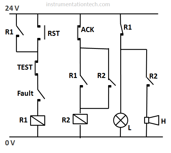
A Test pushbutton is used for checking the functioning of the annunciator .Pressing the TEST button is equivalent to generating an alarm so we can check the annunciator functioning by creating a alarm condition .The annunciator should behave as it is detected a fault .
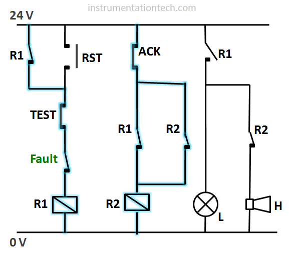
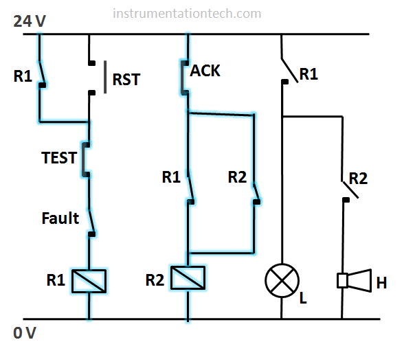
The above figure shows a sample of annunciator circuit for one input only .input is shown in the diagram as fault .It is a contact from field to activate or initiate an alarm .Here open contact is interpreted as fault and close as normal or no fault
Circuit components
R1 Relay
R2 Relay
L Lamp 24V
H Hooter 24V
ACK Acknowledge push button
RST Reset push button
TEST Test push button
Power supply 24 V
circuit operation
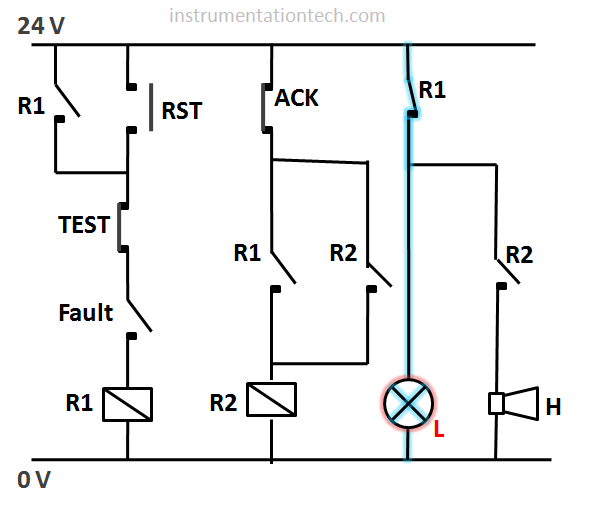
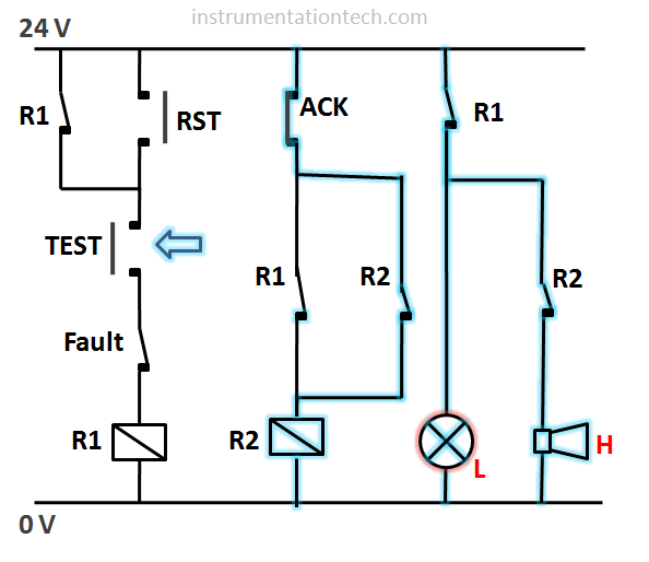
On Switching the power to on, lamp glows by default ..we have to reset the circuit in order to turn off the alarm indication . The alarm indication will not turn off if the fault is present (open contact) see below figure .
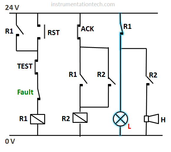
Fault in field changes its status to normal.(closed contact) which means no fault or no alarm condition
Lamp continues to glow .See below figure
We have to press the reset push button to turn of the alarm indication L
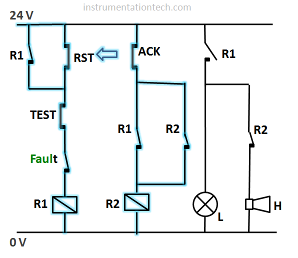
Pressed the Reset pushbutton .
R1 energizes
Alarm indication turns off as the R1 NC changes to open .
R2 also energizes through the acknowledge push button and contact of R1 .And it remains latched by its own contactR2. See below figure .
Releasing the reset button .R1 doesn’t deenergizes as the R1 is latched through its own contact . See below figure .
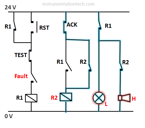
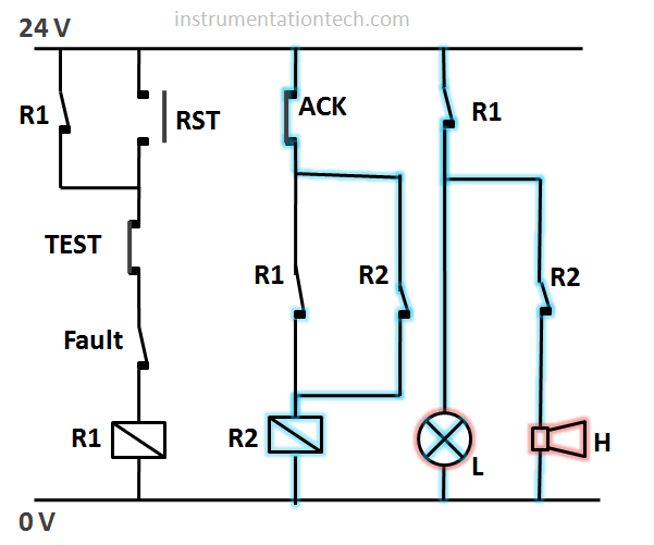
Alarm condition or fault occures .see the contact of fault .R1 deenergizes.Lamp and Hooter activates as the R1 NC contact changes back into close from open .see below figure .
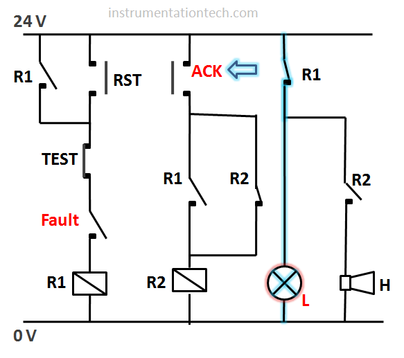
This alarm is generated and it is Pressed indicated by the lamp the acknowledge push button ..on pressing the acknowledge the latching of the relay R2 disabled as the power flow stops .So the R2 deenergizes and Hooter turns of as the R2 contact opens .
Released the acknowledge pushbutton ..
The lamp continues to glow indicating alarm condition .
Fault resets or .Fault normalized .
The lamp still glows indicating alarm condition .
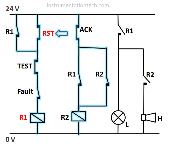
Pressed the reset .Lamp turns off .
R1 energizes
R2 energizes
Cycle continues
.And the circuit is waiting for another fault or alarm .
A test push button is wired in series to the contact of fault .so pressing the TEST push button is equivalent to activating a fault .This function is provided to check the annunciator is properly working .