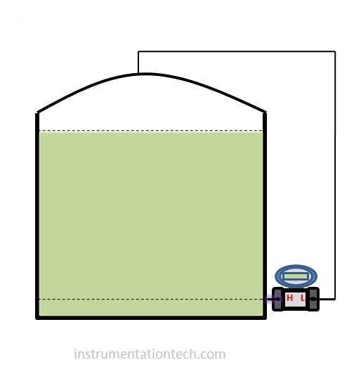
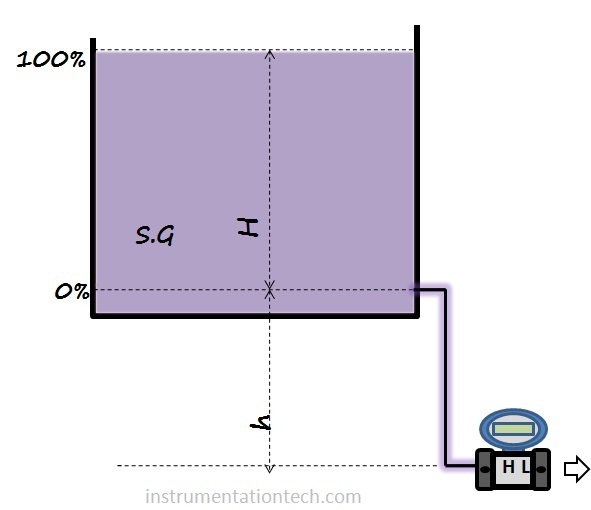
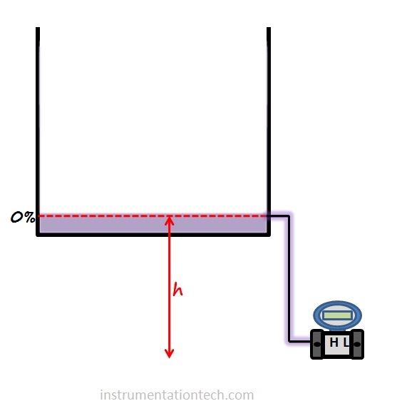
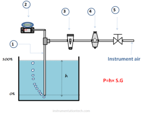
DP Level Transmitter Range Calculation

Differential pressure transmitters are greatly employed in industries for the measuring hydrostatic pressure in a tank thereby finding the level. Range calculation of differential pressure transmitter is an important procedure in process level measurement  applications .In this article we will learn   the concepts of level measurement  using Dp transmitter and DP level transmitter range calculation .

Suppose we have an application like tank level measurement.The liquid level in the tank has to be measured using Differential pressure transmitter. 

What range should  the transmitter have inorder to properly monitor the tank level ????

Or how to calculate the range for Dp transmitter  for tank level measurement application .
What are the data we need for Dpt level range calculation. ?
Let’s go through some basic concepts of Dp type level transmitter range calculations

Hydrostatic method for Level Measurements

 
Main Principle behind hydrostatic type of  level measurement is hydrostatic pressure acting at a point is proportional to the height of liquid above that point and density of liquid.
 
                       P=hρg   
                           Or
                       P=h×S .G
 
 
P is the pressure
 ρ   density of liquid  
g   acceleration due to gravity
S.G  specific gravity.
 
The terms specific gravity and density represents the same physical variables.
 
Both the equations
                         P=hρg     
                       P=h×S .G
 represents the same .The difference is that if we are using the equation P=hρg  then we will get the pressure units in Pa or N/m² etc and we are taking the density for the calculation and its unit is in kg/m³ .Also the factor g=9.8m/s² is taken for the pressure calculation.
 
 
But the equation P=h×S .G     is simple and only specific gravity and height in mm,cm,inches  etc are needed.In this calculation pressure is expressed in  height or heads .units ike mmwc,inches of wc etc .we can convert it further in to any other units by conversion factor if required.
So this equation is preferred for the level range calculation . Because the procedure is simple .
 
If we keep density constant the head pressure is only depend on height of liquid column .measuring  hydrostatic pressure we can easily convert it in to level as both of them keep direct relationship with each other.

DP level transmitter range - selection

Can we Select any DP transmitter  of any range for an application and use it  for monitoring  tank level for a particular liquid?????
The answer is no.
Why???
Because the in head pressure type level measurement,the pressure acting at a point depends on height  of liquid above it and its density.
And we have to consider them.
For example a transmitter calibrated  for the level measurement of diesel tank of  height of 5m is not suitable for the level measurement of water tank of same height .This is because even the tank heights are same specific gravity is different and head pressure acting on the Dp transmitter is different as 
                                P   =  h × SG 
So the calibration or reranging of transmitter is important for a given application .The important data  that we should know before calibrating or reranging of transmitter are

Density/specific gravity of liquid in tank


Density liquid or its specific gravity  both represents the same  physical quantity.

Density

Density   is a measure of how closely particles in matter is arranged.or it is the mass of substance in unit volume.

Density=Mass/volume

Density has units which in SI system expressed in kg/m³

Specific gravity

Density of liquid expressed relative to water density is the specific gravity of that liquid

 S.G =   Relative density

  =density of liquid/density of water 

Being a ratio specific gravity has no units. 

Specific gravity should be non variant for hydrdrostatic type level measurement.

Hydrostatic type  level measurement are applicable when the liquid  keeps it’s density constant .Density  should not be a varying one because a changing density makes level measurement incorrect

Why????

We know hydrostatic pressure at point due to a liquid of height h above is

                 P=hρg  
     
                     Or
  
                 P=h×S .G  
          
 We are measuring hydrostatic pressure and convert it in to level. But the hydrostatic pressure depends on two variables which is height and density or specific gravity.Inorder to measure one variable we need to keep the other constant in magnitude . So we  can calculate the variable by measuring hydrostatic pressure. For level measurement density should be constant and for density measurement level should be constant.

minimum leve and maximum level??

0% and 100%

For calculating the range values LRV and URV of a transmitter,it is essential to know the position of required minimum level and maximum level.

MINIMUM LEVEL    0%

In many case it is very much close to the tank bottom.But in some cases the process or process philosophy  prefer the minimum level some eights above bottom level due to various reasons . For example  some  mounting difficulties may  force us to position the transmitter above the minimum level position  .The transmitter should  sent 0% signal  or 4ma  in this position .And in SCADA or HMI we can conveniently scale this 4ma as per the tank dimensions.

MAXIUMUM LEVEL 100%

At which height the transmitter should send 100% signal or 20ma. Or at which height of the tank is the required maximum level position.we need this position for transmitter s URV  calculation

Open tank and closed tank connections

 OPEN TANK       

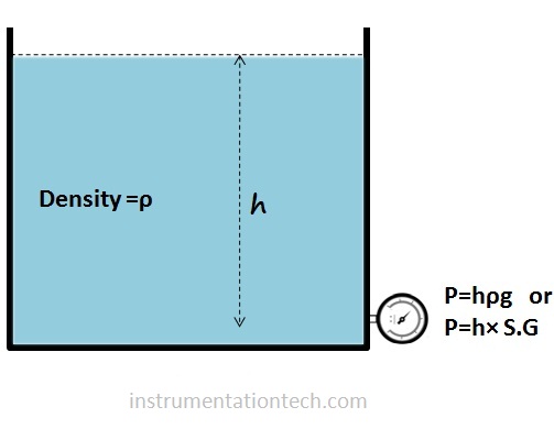
Measurement of level in open tank with  Dp transmitter doesn’t require it’s LP side tapping connected to tank top.It is open to Atmosphere.The differential pressure is the difference in liquid head and atmospheric pressure.(Which is taken as zero in gauge scale.)so HP side pressure is the direct measure of level in the tank  
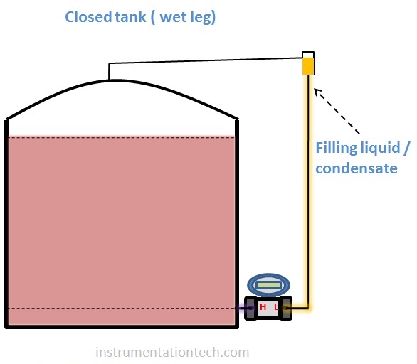
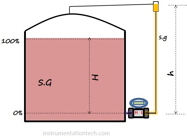
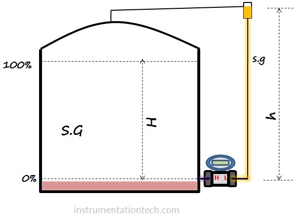
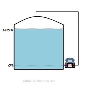
CLOSED TANK

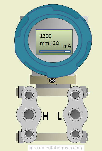
Why we are using DP transmitter and not using pressure transmitter for level measurements?

Incase of open tank .You can use pressure transmitter with proper range for the level measurements .But for closed tank you should use DP transmitter .And tapping from the tank top to the LP side is needed .The reason is below .

In closed tank  there may be some vapour developed  above the liquid surface or the tank itself may be a pressurized one  like in boiler steam drum. A Dp transmitter connected to tank bottom  will experience additional pressure in addition to the differential pressure due to liquid heads .This unknown extra pressure will cause error in the level measurement  .To avoid this LP side is connected to the top of the tank.This method allows the unknown pressure above liquid surface simultaneously acting at both ports of DP transmitter thereby cancelling the effect.So the net differential pressure created in Dp is due to the height of liquid only.

Dry Leg and Wet leg


CLOSED TANK -DRY LEG CONNECTION


Dry leg connection means the leg  or tapping connected to the LP side from tank top is not filled with any liquid or containing any condensate. So it is dry .only gas prassure is acting through this LP tapping to the transmitter.

Dp level transmitter range - Dry leg
CLOSED TANK -WET LEG CONNECTION
 

 In closed tank wet leg connection the LP side tapping is filled with condensate or any other filling liquid.Filling liquid is used  for the protection of transmitters  from direct exposure of corrosive vapours or gas.


DP Transmitter Position

There are number of ways for mounting of  Dp transmitters for level measurement .It is preferred to mount the transmitter at the minimum level position of the tank. But it is not possible always. May be some access problems to the transmitter or mounting or maintenance difficulties or some other reason forces us to mount the transmitter some heights below  the minimum level position .This creates an extra head on the HP side of the transmitter. We have to consider these height because when the level is at 0%  the impulse tube is not empty .It is filled with the process liquid and a head pressure equivalent to that height is acting on the HP side .so at 0%  the Dp is not zero .This extra head is present throughout the range 0-100%.we need to consider this extra head in level range calculations.

Ideal case no suppression.

Transmitter is mounted at the same level as tank minimum level.There is no head pressure acting on the transmitter when the level is at 0%.So the transmitter’s lower range value is zero in any units in this case . Transmitter can be calibrated with

 LRV=0  ,.    URV = h×S.G

Transmitter below minimum level (Zero suppression)


The transmitter is  mounted some heights below the minimum level position

When the level is at 0% head pressure acting on the HP side is not zero  as in the ideal case discussed above.This is because the impulse tube is always filled with  the liquid .A liquid head pressure equivalent to the height of liquid in the impulse tube is always acting on the HP side causing a  head  pressure in addition to head corresponds to the level in the tank. .This head  depends on the height of minimum level position from the transmitter connection port .


Dp level transmitter range -open tank with suppression
 

If  we use a  transmitter which is  calibrated considering  only the height between tank minimum level and tank maximum level then transmitter output will be greater than 4ma at 0% and greater than 20ma at 100%. This is because of the extra head created in addition to the liquid level in the tank .The extra head is  developed because the transmitter is mounted some heights below the tank minimum level and head equivalent to the liquid in the tube is always present in addition to the liquid in the tank. It is always present even if the level in tank is at 0% .so the transmitter have to be properly calibrated or the extra head pressure have to be suppressed to get the transmitter output proportional to the level in the tank  (4ma at 0% and 20ma at 100%) This procedure is called zero suppression.


In older pneumatic transmitters there is a setup provided for achieving this zero suppression called suppression kit. And in modern electronic transmitters we only rerange or properly calibrate the transmitters by considering all the head pressure for calculating LRV and URV..

 In te  figure shown  we are measuring tank level between 0% and 100%.suppose h is the height of liquid in the tank from 0% position.

Let the height of minimum level position to transmitters HP port be H .

So head pressure acting on DP transmitter is

                   H×S.G+h×S.G


But we need only the term H×S.G as it corresponds to the measuring span . The head h×S.G should be suppressed .The procedure of suppressing this extra head created when minimum level position is some height above the transmitter port is called zero suppression.

in the example given in figure LRV and URV  can be  calculated as follows


                LRV=DP at  0%   

                       =  h×S.G – 0  

             LRV = hxS. G 


                    URV=DP at  100%

                  DP    =  HP-LP


                           = (H+h)×S.G – 0

                           =(H+h)×S.G                             

  That is  URV  =(H+h)×S.G             

Dp level transmitter range -open tank with suppression

Zero elevation


In closed tank level measurement using Dp transmitter as discussed earlier there will be filling liquid or condensate liquid in LP side impulse tapping.These condensate or filling liquid is always present in the LP side tapping and we should consider these  liquid for transmitter range calculations as it is a permanent head on LP side.

Dp level transmitter range -wet leg

Let us evaluate the head pressure acting at when the tank level is minimum.

           At 0% level,  

          pressure on HP side = 0

      Pressure on LP side  = height of liquid filled×S.G of filling liquid

So LP side pressure is more  and DP is negative at 0%

So this negative DP should be interpreted as 0% .If e are using a transmitter which is calibrated considering only the head due to the liquid in the tank(as in the ideal case) then Transmitters output will be less than 4ma at 0% and less than 20ma at 100%. This is because the condensate or filling liquid in LP side tube makes the differential pressure  a lesser value .So in order to properly transmitting the level (4ma for 0% and 20ma for 100% )we need to elevate the LRV and URV and the procedure is called zero elevation

Consider the tank shown in figure


On examining we can calculate LRV and URV as

                           LRV=DP at 0%

                                   =Hp-LP

                                   =0 – h×s.g


Dp level transmitter range -wet leg

        URV= DP at 100%

                             =H×S.G- h×s.g


So the LRV calculated is negative and URV may or may not be negative( depends on the heights and specific gravity of filling liquid and liquid in tank).Also we can see that LRV and URV is reduced by a value of  h×s.g when comparing it with ideal case.(no filling liquid in LP side).

Calculation

Calculating the range for Dp type level transmitter means calculating the LRV and URV of  the transmitter.
 
LRV
Lower range value corresponds to 0% output( 4mA).It is the differential pressure created when level is at a position of minimum  or 0%.  
 
URV
upper range value corresponds to the 100% output (20mA).This is the differential pressure created when the level is at 100%.


For calculating Differential pressure in each case we take pressure head acting on HP leg and LP leg of transmitter and subtract .
 

DP=HP-LP

HP = pressure acting at transmitters HP side
 
LP=pressure acting at transmitters Lp side
 
(Here HP is only to indicate pressure acting on high pressure side and LP that on LP side .Pressure acting on HP side may not be always greater than LP side.It depends on the tapping conditions like dry leg or wet leg,filling liquid in wet leg etc .
see closed tank level calculation-wet leg)


In short to calculate range for a level transmitter remember  these points .


For calculating pressure acting at  HP side  and LP side  use equation h×SG.

1.calculate Dp at 0% which is LRV

2 .Calculate DP at 100% Which is URV

3 .DP=HP-LP

4.For  calculating HP  and LP use equation P=h×S .G