DP type level transmitter range calculations-part 3 closed tank
DPT range closed tank/calculation
This article explains range calculation of differential pressure transmitter for closed tank level measurements .If you want, read the basics and open tank level measurements here.
To get the range for the transmitter suitable for level measurement of a tank, ,we need certain data like
1.density of the liquid,
2.minimum level position or position of 0% level
3.maximum level position or 100% position
4Height or position of minimum level (0%) from Transmitter HP port
5.filling liquid density ( if closed tank wet leg)
6.Liquid height in wet leg
Note: The liquid density should be non variant for hydrostatic pressure type level measurement applications .
Calculation procedure
1.Calculate head pressure acting on the HP side when level is at 0%
2.Calculate the head pressure acting on the LP sidewhen level is at 0%
3.Find DP at 0%
DP=HP -LP at 0% which is the LRV
4.Calculate the head pressure acting on the HP side when level is at 100%
5.Calculate the head pressure acting on the LP side when level is at 100%
6.Find DP at 100%
DP=HP -LP at 100% which is the URV
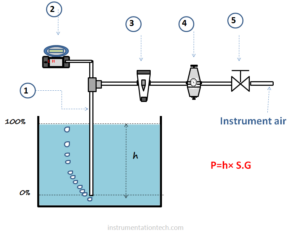
For calculating pressure acting on HP port and LP port use equation
h×S.G
Note:In our calculations HP and LP represents only pressure acting at the transmitter’s HP port and LP port respectively. And also HP side pressure may not be always greater than LP side pressure. see in wet leg calculations.
So you just remember
HP =pressure acting at HP port
LP= Pressure acting at LP port
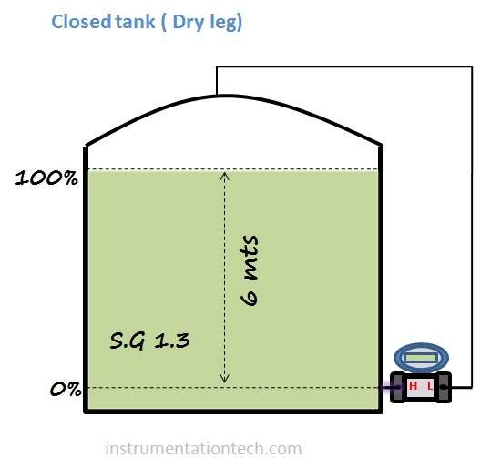
Example 1: Closed tank (dry -Leg)
calculate range for the transmitter which is connected to measure level of a closed tank.The transmitter is mounted at the bottom and the Hp side tapping is taken from the minimum level position 0%.also transmitter is positioned at the minimum level.See below figure .
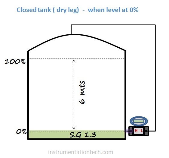
Find LRV - DP at 0%
To find the lower range value calculate differential pressure when the level is at 0%.calculate the hydrostatic pressure acting on the high pressure side and low pressure side when level is at 0%
Then LRV = DP at 0%
= HP-LP at 0%
See figure above .Level is at 0% .we need to calculate the DP at this position which is the LRV .
LRV=DP at 0%
Head Pressure on HP side
HP = h×S.G
= 0 ×1.3
= 0 mmwc
Head Pressure on LP side
LP = 0 mmwc
( Note:we need not consider vapour or gas pressure which develope above liquid surface as It’s effect will be cancel by connecting LP port to tank top)
DP = HP-LP
= 0-0
= 0 mmwc
At 0% , DP = 0 mmwc
That is LRV = 0mmwc
Find URV - Dp at100%
To find the upper range value calculate differential pressure when the level is at 100 %.calculate the hydrostatic pressure acting on the high pressure side and low pressure side when level is at 100%
Then URV = DP at 100%
= HP-LP at 100%
See figure above . Level is at 100% .We should calculate the differential pressure acting at this condition .
URV=DP at 100%
Head Pressure on HP side
HP = h×S.G
= 6000 ×1.3
=7800 mmwc
Head Pressure on LP side
LP = 0 mmwc
DP = HP-LP
= 7800-0
= 7800 mmwc
At 100% DP = 7800 mmwc
That is URV = 7800mmwc
So we need to calibrate the transmitter with
LRV=0 mmwc corresponds to output 4 ma
URV=7800 mmwc corresponds to output 20 ma
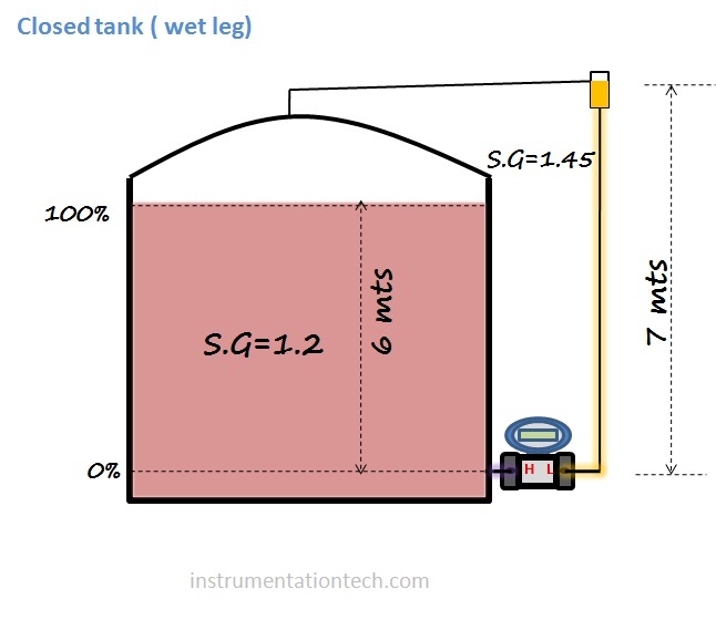
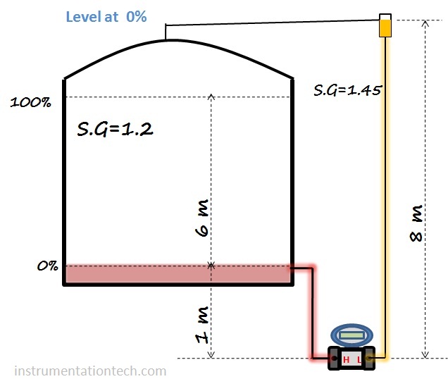
Example 2 Closed tank (wet leg)
We have to calculate range for the transmitter which is connected to measure level of a closed tank.The transmitter is mounted at the bottom and the Hp side tapping is taken from the minimum level position 0%.also transmitter is positioned at the minimum level.Lp side is filled with liquid .see below figure for necessary data
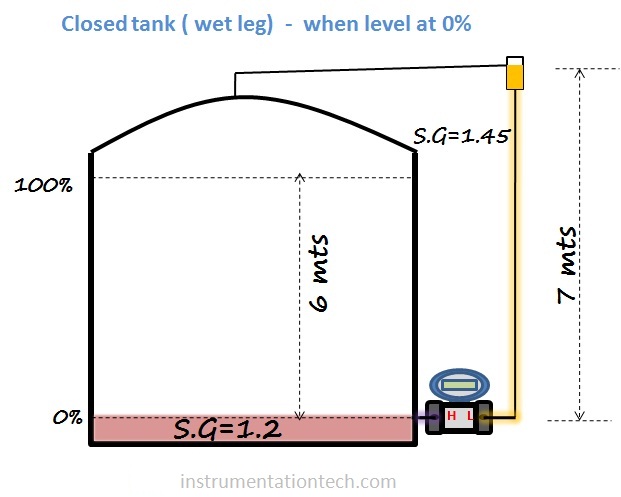
LRV DP at 0%
find the lower range value calculate differential pressure when the level is at 0%.calculate the hydrostatic pressure acting on the high pressure side and low pressure side when level is at 0%
Then LRV = DP at 0%
= HP-LP at 0%
LRV=DP at 0%
Head Pressure on HP side
HP = h×S.G
= 0 ×1.2
= 0 mmwc
Head Pressure on LP side
LP = h×S.G
Note : There is always a constant head pressure acting on the LP side .This is due to the constant head of filling liquid in the LP side tubing .
LP = 7000 ×1.45
= 10150
DP = HP-LP
= 0-10150
= – 10150mmwc
At 0% , DP = – 10150 mmwc
That is LRV = – 10150mmwc
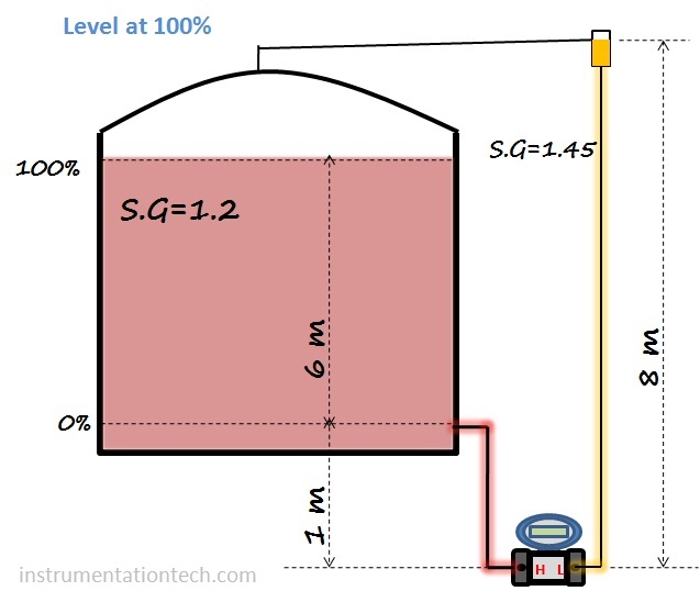
URV= Dp at 100%
To find the upper range value calculate differential pressure when the level is at 100 %.calculate the hydrostatic pressure acting on the high pressure side and low pressure side when level is at 100%
Then URV = DP at 100%
= HP-LP at 100%
URV=DP at 100%
Head Pressure on HP side
HP = h×S.G
= 6000 ×1.2
= 7200 mmwc
Head Pressure on LP side
LP = h×S.G
= 7000 ×1.45
= 10150mmwc
DP = HP-LP
= 7200 – 10150
= – 2950 mmwc
At 100% , DP = – 2950 mmwc
That is URV = – 2950 mmwc
So we need to calibrate the transmitter with
LRV= – 10150 mmwc corresponds to output 4 ma
URV= – 2950 mmwc corresponds to output 20 ma
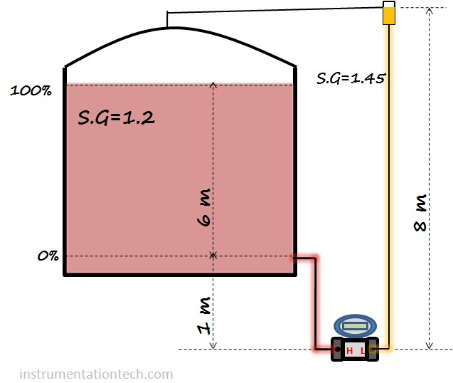
Example 3 Closed tank (wet leg)
We have to calculate range for the transmitter which is connected to measure level of liquid in a closed tank.The transmitter is mounted at the bottom and the Hp side tapping is taken from the minimum level position 0%.also transmitter is positioned 1m below the the minimum level.Transmitters Lp side leg is filled with liquid . see below figure for necessary data.
find the lower range value calculate differential pressure when the level is at 0%.calculate the hydrostatic pressure acting on the high pressure side and low pressure side when level is at 0%
Then LRV = DP at 0%
= HP-LP at 0%
LRV=DP at 0%
Head Pressure on HP side
HP = h×S.G
= 1000×1.2
= 1200 mmwc
Head Pressure on LP side
LP = h×S.G
= 8000 ×1.45
= 11600
DP = HP-LP
= 1200-11600
= – 10400mmwc
At 0% , DP = – 10400 mmwc
That is LRV = – 10400 mmwc
URV= Dp at 100%
To find the upper range value calculate differential pressure when the level is at 100 %.calculate the hydrostatic pressure acting on the high pressure side and low pressure side when level is at 100%