MAGNETIC FLOW METER

  Magnetic flow meter , a device commonly used in many industries to measure the flow rate of fluids in pipelines .The principle behind this type of flow measurement is electromagnetic induction.

Faraday's law of electromagnetic induction

 An emf will induce in a conductor when magnetic field linked with the conductor changes.
 
A conductor of length l moving in a magnetic field of strength B with a speed of  v m/s . Then the emf induced across the conductor is given by
 
     e =Blvsinθ 
 
where θ  is the angle between magnetic field direction and direction of conductor motion
magnetic flow meter principle - emf generated by a moving conductor
The direction of induced emf is given by Fleming’s right hand rule.
 
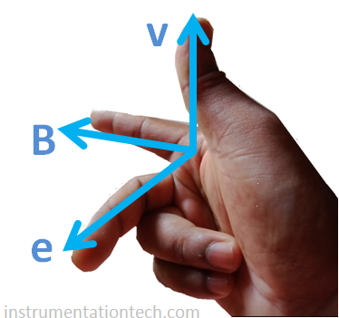
Fleming’s Right hand rule 
 If  we  held our right hand with the thumb,index finger and middle finger mutually perpendicular to each other  and if the thumb represents the direction of motion of the conductor  in a magnetic field,  index finger represents the  direction of field ,then the middle finger gives the direction of induced emf .
 

Working of magnetic flow meter

 A fluid with a required minimum conductivity  is passed through the  flow tube of magnetic flowmeter  .The inside  of the flow tube assembly is subjected to a magnetic field of required strength .This is achieved  by a powering a  coil enclosed in flow tube housing .A constant known current is fed in to the coil and coil gets magnetized providing a magnetic field to the flow path .. The liquid  should have  a  minimum conductivity so that it acts as a conductor which induces  a voltage  while moving in  the magnetic field .So the movement of the conductor induces an emf .  pick up electrodes are properly  embedded in the housing of the flowmeter .They are placed right angle to the flow direction . Pick up electrodes  carry the induced voltage which is created due  to the  movement of fluid .The voltages  created are in  the order of the millivolts .

Flow and output voltage relation

 
The  induced  voltage is proportionally  to the flow velocity and  is given by the expression,
 
e =Blvsin θ 
 

l is the length of the conductor or pipe diameter D. As the magnetic field and velocity vector are mutually perpendicular  in magnetic flow meter,θ =90°

Or sin θ = sin90=1
 

e =BlV

 or

 e = BDV
 Here the terms pipe diameter D, strength of magnetic field B are constant 

e= constant×v
Or v= constant×e

Flow =V.A

            = Constant × e

Flow = K × millivolt

As magnetic flow meter responds to the velocity of the fluid it is a volumetric flow measuring device and not the mass flow .


Flow Tube Assembly

The part hrough which  fluid passes.coils and pickup electrodes are fabricated inside of this part .

Magnetic flow meter
A magnetic flowmeter - flowtube make :khrone

Coils 

In flowmeter, permanent magnetic field is achieved by passing an exciting current to a properly constructed coils coils are arranged top and bottom  portion of the flow  meter to create the magnetic e field in a direction perpendicular to the flow . current may be ac or dc pulsating.The exciting current creates  a permanent magnetic field through which fluid passes thereby inducing a voltage proportional to fluid flow.

Why pulsating DC ???

Although DC creates magnetic field the permanent polarity of DC current makes polarisation of ions or fluid particles thereby generating electrochemical effect .This causes the ions to move to a specific electrode according to their polarity  and accumulates there causing the measurement error.This effect can be over come by giving a pulsating DC which reverses it’s polarity at certain frequency thereby not allowing the ions to deposit on electrodes.

Pick up electrodes

The voltage induced across the conductor (Liquid  layer )is picked by  electrodes arranged   sideways  in  the flowtube .It is perpendicular to the fluid flow and magnetic field .The inside of the flow tube is electrically  isolated from the conducting fluid by teflon lining .only  the pick up electrodes is able to make electric circuit with the liquid .All other part of the flow tube is isolated from the mv output .


CONVERTER

Millivolts signal from the electrodes are fed in to the converter unit,for signal conditioning,and transmitting as a standard signal like 4-20ma .Further converter unit serves as a interface unit for transmitting the signal,for supplying excitation current to the flow tube ,and for programming various parameters through front display panel etc  .Converter unit either constructed as a seperate unit from flow tube or it is integrated to the flow tube . see below figures.


1.Converter unit integrated with the flow tube

magnetic flow meter -integrated design

2. converter and flow tube serves as a seperate unit.

magnetic flow meter - converter and flow tube separate

Wiring

The following  basic wiring  and signals   are needed for the operation of the flow meter as a sensor and a transmitting device .

 Power supply to the converter

Coil exciting current

Millivolts output


Transmitted signal from converter to  control room or monitoring devices. ( 4-20 ma )

 The below figure gives a overview of the basic connection details for a magnetic flow meter .


magnetic flow meter earthing


Proper earthing should be done for magnetic flowmeter for its correct operation . Magnetic flowmeters output is  small  electric signal which is of the order of few millivolts . other stray voltages or electrical noises may affect this signal .Industrial environment are subjected to disturbances like  these electrical noises These noises are actually unwanted electrical voltages . They circulates through the conducting parts like pipelines.They also pass through the conducting liquid .These noises should not affect the magnetic flowmeter performance .And they should be properly eliminated before they reach to the pick up electrodes .This is done through proper earthing .By this we can eliminate the unwanted electrical noises reaching the pickup electrodes .

Grounding for conducting pipelines


In case of  metal pipelines  which are conducting , they should be grounded .This can be done by making the ground connections  to  the flanges . See below figure..

Grounding for non conducting pipelines


For non conducting pipelines,the electric noises  through the liquid can be grounded  by using grounding rings .The grounding rings is  arranged at ends of the flow tube .And they come in contact with the liquid . Electric noises pass through the liquid is grounded  through this grounding rings .see figure .